As everybody knows, the best way to join things in the world is with screws. Therefore, this post will be about modelling threaded parts in Blender for 3D printing. Printing threads directly is often more convenient and cheaper than gluing in threaded inserts or cutting threads manually after printing. However, I make no claims about their strength. Also it maybe impossible to print very small screws, depending on printer’s resolution.
In Blender it is easy to model any standard or costume screw of any profile, any number of threads, left/right handedness, etc., … Imagiganation is the only limit.

Notice: actually i don’t know if there is some official way “how to model screws in Blender”, and too lazy to google that. So i describe my own method, that i used with older Blender versions, and adapted, as Blender gained new functionality. With this method, it is easy to modify any screw parameter later and reprint the part if the first attempt does not fit.
As an example i show how to model very useful thing – cylinder that screws on plastic 5 litre water container.
Measuring
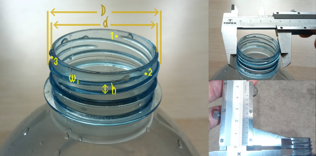
First step is to measure existing bottle neck threads. For this task, I used a caliper, but a simple ruler would probably be enough. Basically it is sufficient to measure 4 dimensions:
- d – Bottle neck diameter without threads (it can be measured at very top of neck, since there is some distance before threads starts).
- D – Bottle neck diameter with threads.
- h – Distance between centres of consecutive threads (step).
- w – thickness of the thread (how wide is thread near the bottom).
Measurements do not necessarily have to be very precise, they can be rounded up (we don’t try to make some vacuum sealing cap). Probably only h should be more accurate, since if it drift in any direction, it wouldn’t be possible to fully screw printed part on existing bottle neck, especially if it is long.
Also it is useful, to notice how many threads bottle have (n). While ordinary bolts usually have single thread, things like large water bottles or jars somehow have more. In this case there is three.
Modelling
Basically, two parts are needed: the thread and the cylinder. Both can be modeled using the same principle: first, draw a 2D profile in mesh edit mode, then “lift” it into 3D space using modifiers.
Thread modelling
So lets begin by drawing 2D thread profile.

- Add simple plane with diameter equal to d that is aligned to front view.
- Subdivide that plane.
- Delete all vertex except one vertex at the right.
- Draw 2D profile of the thread, by extruding that one vertex that was left.
Ideally drawing should follow real profile, but since we modelling loose screw, it is allowed to use some imagination. As you can see in the image, i modelled upper side of profile (that corresponds to hanging side of thread ridge) slanted, so it can be printed without supports. Luckily, this matches reality quite well. It is visible to the naked eye that one side of the bottle-neck thread is also slanted, while the other side is mostly flat. The drawn profile should be made slightly larger than the measured dimensions to provide a better fit.
Now we can “screw” it to 3D space by adding necessary modifiers:
1. Screw modifier (obviously)

Angle: 360° / n
Or full circle divided by number of threads. If there is 3 threads, than angle will be 120°
Screw: h
Or distance between centres of consecutive threads. Use negative number for left-handed screws.
Iterations: 7
That depends on how long you want the screw to be. Increase this value until the generated thread height exceeds the required screw length.
Axis: Z
It is Z axis if profile is modelled in front view, and there is no additional rotation transformation.
Steps: 22
More steps – larger resolution. I chose 22 – that is mostly random.
Normals > Calculate order
This checkbox must be checked, since our thread profile is mesh.
Normals > Smooth shading
This can be unchecked for clearer visibility.
2. Geometry nodes – fill endings

After the Screw modifier, the thread is already visible. However, its ends remain open. Since non-manifold meshes can interfere with later Boolean operations, the ends need to be capped. I use a simple Geometry Nodes setup to do this.

It extrudes open edges (that have only one face attached), and then merge vertexes in them by distance – effectively closing those holes. This works, since endings of thread is far away from each other, and thread profile is convex polygon. If those conditions is not met, we should use some more sophisticated node setup.
3. Array modifier
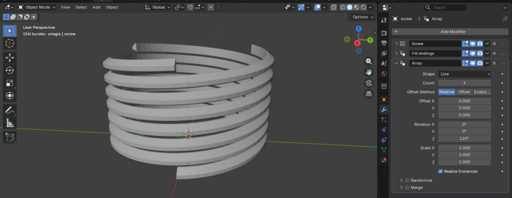
This required only, if screw have more than one thread.
Count: n
Number of threads on screw. Three for our case.
Offset: 0
Zero to all axes.
Rotation: 360° / n for Z axis (120° for our case), 0° for X and Y.
Scale: 1 for all axes.
In older Blender versions, array modifier was much more limited, and don’t have the rotation capability, so in that case it is possible to use “object offset” with rotated empty object, or just create two linked copies of thread profile, and rotate them manually by 360° / n.
Cylinder modelling

Our threads is finished! Its time to create cylinder. For this task we basically use the same method as for threads: start from plane and draw cylinder profile. Internal side of profile can be slightly enlarged, and lower side is slanted for better bottle neck insertion and to accommodate enlargement of bottom layer when printing part with cheap FDM printer.
When 2D cylinder profile is finished, we can add modifiers to it.
1. Screw modifier. Again. This time with different parameters.

Angle: 360°
Full circle.
Screw: 0
Since we making cylinder, not screw.
Iteration: 1
Since we making closed cylinder.
Steps: 66
Since there is 3 threads, it is probably best to use x3 times number that we used in thread modifier (22), to create consistent geometry.
Normals > Calculate order
This checkbox must be checked, since our thread profile is mesh.
Normals > Smooth shading
This can be unchecked for clearer visibility.
Normals > Flip
For some reason, flipping normals directions sometimes helps prevent Boolean modifier errors later, such as strange steps in the thread groove.
2. Boolean modifier

This modifier will engrave thread on inner cylinder wall.
Operation type: Difference
Object: Object of threads, that we created earlier.
Solver: Manifold
This should work since our cylinder and threads counts as manifolds, if everything done correctly. If for some reason it is not working, or if we modelling in earlier Blender version, it will be fine to use “Exact” solver instead.
3. Weld modifier
It is not absolute necessary, but it fixes duplicated vertex that boolean modifier sometimes mystically produce. Just set distance, to very small value, to avoid accidentally merging some innocent vertexes.
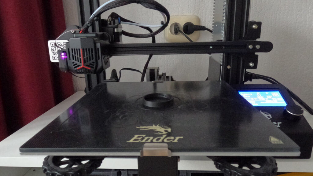
The End
And that’s it, our threaded tube is finished! Now we can print it and make some bottle hourglass, since it somehow screws onto both ends, even though the thread profile is not symmetrical in reality 🤔.
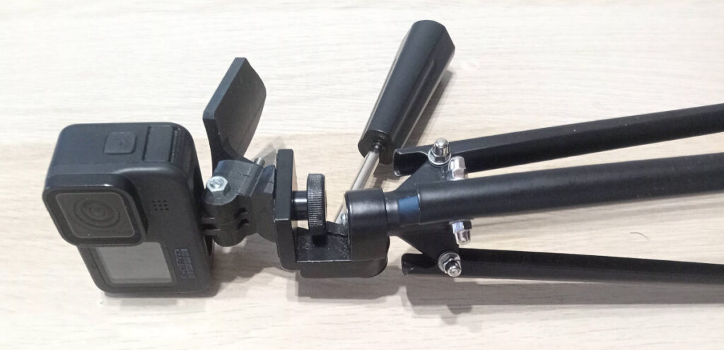
Additional note: Not saying, that this bottle cap is not useful, just want to pay attention that same modelling principles apply to any other threaded parts, like for example adapter for mounting go-pro camera to standard tripod.